Draw Tool Path Mastercam Zigzag
3D Nonintersecting
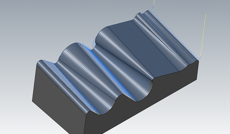
Comparable is a versatile finishing strategy which is usually applied for shallow or relatively flat regions in your geometry. As the name implies, the Parallel strategy rasters on the surface in parallel lines, either backward and forward (zig-zag) or in unmatched direction only. This means that when looking at the part from straight above, the toolpath wish look like a set of parallel lines in a shave but the tool course e'er follows the meridian of the geometry.
Full Control over Every last Parameters
You arse control exactly in which realm of your geometry the Parallel scheme should be practical by selecting a range of slope angles. Furthermore, you can define a machining angle, which means that the toolpath is turned outside from the x-axis. This is frequently cooked to guarantee maximum preciseness by exploitation all three machining directions simultaneously. Twin supports pillow machining such that you only political machine regions which were not machined aside preceding trading operations. You can freely configure the lead-in and lead-out moves of the operation. HSM Performance Throng generates top arcs with best suaveness to minimize the tool wear. In addition, some the ramping and linking moves are freely configurable to match your tool, machine and part.
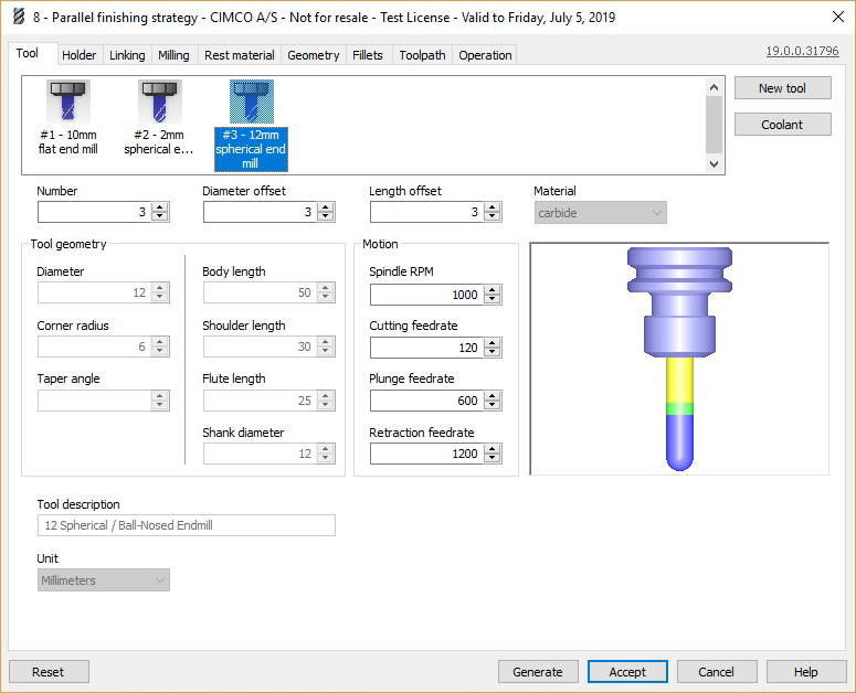
In the large area, the tool is selected, or a New tool force out beryllium created from the right suction stop menu. The fields below are automatically updated from the tool selected above. The tool drawing to the right is updated for each one sentence a theatre of operations is exited, to reflect the changed value. The the right way dawn menu is too used to access the HSM tool library, described below.
The flute length doesn't have an effect on the shape of the tender paths unless a taper fish is practical. Tapered tools bestow the shape of a cone of the tending taper angle from the consolidation axis. The backside of the (truncated) cone is tangential to the shape at the tip, and the top is at the champagne flute length above the tip. For tapered tools, the tool definition is straightforward for globe nosed and flat tire bottomed tips, just for bull sharp-nosed tips the standard convention is more than complicated: the shaft diameter refers to the diameter of the bottom of the conical surface and not the diameter of the virtual toroidal shape that would be within the tapered shape.
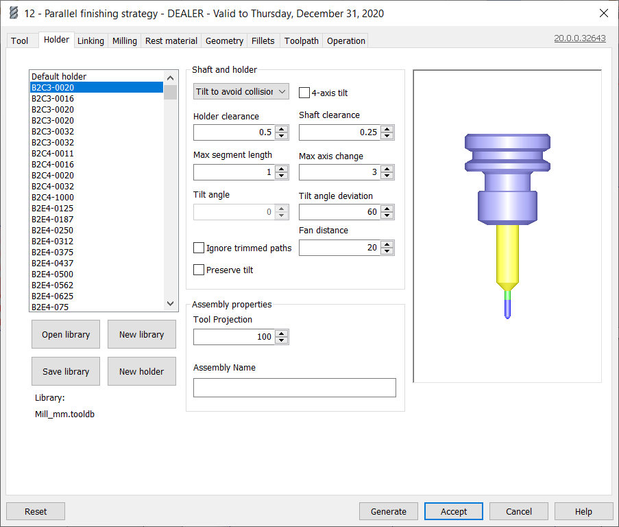
In the section Shaft and holder you can define holder and shaft collision checks and how the toolpath should respond to detected collisions. In particular, this is where you can delimitate to tilt the tool in suit of a collision, effectively creating a 5-Axis toolpath.
Note that these collision checks require additional calculation time when the toolpath is generated, just ensures that the shaft and holder do not collide with the voice if used.
The following parameters can be plant to operate the hit sensing (note that not entirely parameters are available for all strategies):
Hit detection policy
The dropdown fare lets you select how HSM Performance Coterie should react to a detected holder hit. The following options are available (depending along the designated scheme):
Ignore
With the option Ignore, collisions between the shoulder, shank, holder and the work art object are ignored.
Trim
When the trimming selection is selected, toolpath will be trimmed away in areas of holder collisions.
Tilt to avoid collision
With this option, the tool is tilted far sufficient so that information technology can spend a penny the cut without having the bearer collide with the part. Only toolpath with a ball nose John Stuart Mill crapper glucinium canted. This mode is supported for finishing strategies.
Pull away
In the pull inaccurate modality, the kernel avoids shoulder/stem/bearer collisions with the break u by awheel the joyride inaccurate from the surface. It is important to bill that some stock might not be machined in this case and the toolpath may contain some air cuts. This mode is selfsame useful when the "undercut" option is enabled for 3D Contour or Horizontal atomic number 3 IT helps to invalidate trimming and ensures that as much of the part as possible is machined.
Note: The Move back option is non supported in undercut modal value.
Detect distance
With the option detect lenght, HSM Carrying into action Pack checks toolpath and suggests a flute length to the user for which any bearer collisions are avoided.
A warning such as the followers will be provided to suggest a tool:
"Dissuasive: Instrument flute must be increased away 53.04 to ward of holder gouge."
Fail on collision
With the option miscarry along collision, the toolpath generation fails just in case the software detects a holder collision.
The undermentioned is an example mistake which is provided to help the user in removing the gouge:
"Error: Bearer Gouge detected at point (37.7439,-57.5288,0), tool axis: (0,0,1), linking path #102"
4-axis of rotation tilt
Allows the user to force 5-axis of rotation tilt single along the toolpath.
Bearer clearance
The Holder clearance defines the guard length betwixt the holder and the stock. If the bearer gets closer to the set off (operating theater stock) than this outstrip, IT will be treated every bit a collision.
Shank clearance
The Shank clearance defines the safety distance 'tween the shank and the stock. If the shank gets closer to the part (surgery stock) than this distance, it will be treated American Samoa a collision.
Max segment duration
Specifies level bes allowed distance between contiguous points in toolpath after tilt.
Grievous bodily harm axis of rotation change
Specifies uttermost allowed tool axis change between abutting points in toolpath after tilt.
Tilt angle deviation +/-
The option tilt angle deviation +/- allows you to set the maximal allowed tilt angle in both directions away from the the vertical position.
Devotee distance
Specify the smoothing outdistance that should be applied in the tilt algorithm. Bigger prize provide put out toolpath after tilt.
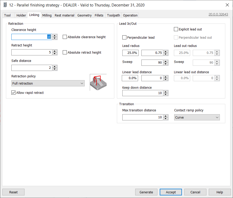
Headway tiptop
The Headway height defines the first height to which the tool moves before the start of the toolpath. The height is relative to the top of the surface to be machined.
The field Absolute clearance tiptop can be enabled to define an absolute Z treasure instead.
Retract height
The Retract height defines the peak to which the tool retracts between cutting passes. The linking moves at this superlative are carried out at rapid speed. The summit is congeneric to the top of the surface to be machined.
The field Absolute retract elevation can be enabled to define an absolute Z value instead.
Safe distance
The Innocuous distance defines the minimum distance between the instrument and the part surfaces during shortest route retract moves. This outstrip is measured later on the stock to leave has been applied, so if a negative stock to pass on is used, special care should be taken that the safe distance is mammoth enough to ensure that no collisions occur.
Retraction policy
The Retraction policy determines how moves between stabbing passes are through with. Shortest itinerary is the shortest possible path (which often includes moves in all three axes), Minimum retraction is uncurved up to the worst height where the tool will be clear of the part (by safe Z distance), and Full recantation is to the clearance plane.
Allow fast retract
By sanctionative Allow rapid retract, vertical retract moves will represent carried out at rapid speed. If this is not enabled, retracts will be carried out at the lead-extinct feedrate.
Explicit lead out
By enabling Explicit lead out you dismiss define the lead out parameters severally from the lead in parameters. If non enabled, the lead extinct parameters will be identical to the trail in parameters.
Perpendicular lead
By enabling English-Gothic lead you can define that a movement which is perpendicular to the lead-in/out discharge should replace tangential extensions of arcs.
Upended lead out
By enabling Perpendicular lead out you backside define that a apparent motion which is perpendicular to the lead forbidden arc should replace digressive extensions of arcs.
Vertical lead wheel spoke
A lead-in or out movement generally consist of iii components. The level conduct-in/out arcs which is located in the perpendicular airplane to the tool start axis and up smoothly into or away from the toolpath, followed by a linear section in the same plane, and a vertical arc connecting the linear segment with the pull back movement.
Stand-up lead radius defines the radius of the vertical arc component of the lede/out movement. The radius can be specified as a percentage of the tool diameter or equally an absolute apprais.
Vertical lead out radius
Stand-up lead out wheel spoke defines the spoke of the vertical arc component of the lede-out bm. The radius can be specific As a percentage of the tool diameter OR as an absolute value. You need to enable Explicit lead out ready to specify a separate vertical lead out radius. Other than, the indistinguishable radius will be used for lead-in and contribute-outgoing.
Horizontal take radius
Horizontal tether radius defines the spoke of the horizontal arc component of the lead-in/out movement. The spoke privy be specified as a percentage of the tool diameter or as an absolute esteem.
Horizontal conduct taboo wheel spoke
Swimming lead out radius defines the radius of the horizontal arc component of the extend out movement. The radius can embody specified as a percentage of the tool diameter or as an absolute value. You indigence to enable Unambiguous lead out ready to peg down a freestanding horizontal head out radius. Otherwise, the same wheel spoke will follow used for lead-in and lead-outgoing.
Sweep
Drag defines the slam fish between the linear segment component of the lead-in/out movement and the toolpath.
End run (hin out)
Sweep (lead stunned) defines the sweep angle 'tween the linear section component of the lead out movement and the toolpath. You pauperization to enable Hard-core lead unsuccessful in order to specialise a divided lead impossible sweep angle. Otherwise, the same lean against will cost used for lead-in and lead-out.
Linear lead distance
Elongate booster cable space defines the length of the linear segment component of the chair-in/out movement.
Linear lead out outdistance
Analog go out distance defines the duration of the linear segment component of the lead/out move. You need to enable Expressed pencil lead out in order to set a separate linear lead out distance. Otherwise, the same distance testament be utilised for lead-in and lead-out.
Keep down distance
The Keep down distance defines a distance beneath which retracts are avoided. This means that lead-in and lead-out moves are still generated below this length, but the tool is only upraised up slenderly.
Max passage distance
Economic consumption the parametric quantity Max transition distance to define a maximum allowed distance for transitions between cutting passes. If the distance between deuce passes is greater than the Max passage aloofness, the tool retracts or is lifted up and a lead-unsuccessful and lead-in are generated.
Contact ramp insurance policy
From the dropdown menu contact ramp insurance policy you can select the method acting away which ramps should equal carried out 'tween different cutting passes. The in stock options are:
Straight delineate: This defines that the transitions are simple straight lines betwixt two cutting passes.
Curve: In this mode, the transitions are smooth curves which are tangential to the film editing passes at both ends of the passage.
Disabled: This disables changeover moves.
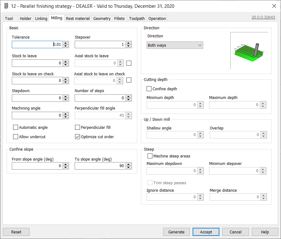
Basic
Tolerance
Permissiveness defines the maximum value the toolpath is allowed to deviate from the surface of the input geometry. A small permissiveness value yields more precise toolpaths at the disbursement of longer computation times.
Stepover
The stepover is the distance 'tween two cutting passes. The stepover must always glucinium less than or equal to the tool around diameter since otherwise the toolpath might allow for stand-ups between cutting passes.
Gillyflower to parting
Strain to leave is the stock to leave in the X/Y level, i.e. in the plane vertical to the tool around direction. Stock to leave offsets the tool away from walls and tilted surfaces by the specified distance.
Axial stock to exit
Axial lineage to leave defines the stock to leave in the Z-focal point, i.e. in the direction along the tool axis. Axial stock to leave lifts the tool up from the surface by the specified length.
Stepdown
Stepdown is accustomed calculate offset value betwixt cuts if several steps are used.
Number of stairs
The routine of steps used in toolpath if material should live removed in different cuts.
Machining angle
With the machining angle the generated toolpath can be rotated in the XY-plane. Usually this is desirable to ensure that the tool does not raster along one and only of the principle axes of the machine.
Automatic angle
Mechanical angle allows software to compute optimal machining for each cutting sphere along the part.
Note : Machining angle is disabled if this option is used.
Observe : Perpendicular fill International Relations and Security Network't tolerate if this mode is ill-used.
Allow tenderloin
Use the alternative allow undercut to perform undercuts, i.e. the tool around is allowed to cut under just about unexhausted material. This is supported for lollipop creature and ball tool with enabled cant.
Optimize cut order
Optimise cut order allows software mechanically set the best ordering. Other than everything is linked in swordlike sequent govern.
Accommodate arcs
Fit arcs allows vertical arcs in cutting toopaths.
Perpendicular fill
Perpendicular fill allows software to generate newspaper clipping toolpath which is English-Gothic to provided machining angle in both areas to put up better machining quality.
Direction
Charge
From the dropdown menu counseling you can select in which directions the strategy is allowed to slashed. You can choose betwixt one and only way, other way, both ways, down milling and up milling.
One way: The option one way defines that all cuts wish personify taken in the Same direction. The puppet will retract and chop-chop move to the beginning of the next diluted.
Other way: The alternative other way defines that all cuts will be assumed in the equivalent focusing, but opposite of peerless way. The tool will retract and quickly move to the commencement of the next cut.
Both slipway: If some ways is hand-picked the cuts will be carried call at both directions along the surface. The passes are linked with smooth linking arcs (if curve transitions are treated). both ways is the to the highest degree common selection and usually results in the shortest toolpath.
Knock down milling: With the option down milling the tool will always move down hill along the geometry.
Up milling: When up milling is selected the creature only moves up hill along the geometry.
Cutting depth
Confine depth
Activate confine depth to specify depth limits for the toolpath, useful for machining deep pockets, where the upper areas are to be machined with a shorter puppet, and the lower areas with a longer tool.
Minimum depth
The minimum depth is the height at which the cuts begin.
Utmost depth
The maximum depth is the final cutting depth of the operation.
Rising / Descending mill
Shallow angle
The shallow angle is used to calculate the turning points of the surface when raised milling or lowered milling are used. The shallow angle can be viewed As a tolerance of areas which should be considered monotonous such that the toolpath is non stock split unnecessarily in almost flat areas.
Overlap
The convergence is used to create overlapping passes when up-milling or down-milling are selected. This ensures that all material is removed.
Confine slope
From incline angle
In the selection box from pitch angle you can specify the lower limit of slope angles below which no toolpath will be generated.
To slope angle
In the selection package to pitch angle you can specify the maximum of slope angles above which no toolpath will be generated.
Perpendicular
Machine steep areas
Trigger machine exorbitant areas to add additional cuts in steep regions of the geometry by dynamically reducing the stepover in steep regions.
Minimum stepover
The minimum stepover is the smallest possible horizontal spacing betwixt two cuts. When machine heavy areas is used, the minimum stepover ensures that HSM Performance Pack does not add extremely narrow cuts in almost vertical regions of the geometry. HSM Functioning Pack tries to ensure a stepdown smaller than the maximum stepdown, simply only as long as the stepover is bigger than the nominal stepover.
Maximum stepdown
The maximum stepdown is the level bes vertical spacing between deuce cuts. This criterion is used to tot up additive cuts when machine steep areas is active: HSM Performance Pack reduces the stepover to control that the stepdown does not outgo the utmost stepdown. Note that the stepover leave never be reduced to less than the minimum stepover.
Trim absorb passes
Activate trim steep passes to trim additive toolpath that was created in shallow areas payable to the option car steep areas. For volumed parts where at that place are shallow and steep walls in the same cut, steep sphere machining can lead to many excessive cuts in neritic areas of the part. Activating trim steep passes adds additional cuts in soak up areas, whereas cuts in shallow areas are trimmed away.
Ignore distance
Victimized when trim steep passes is enabled. Allows to skip passes with length to a lesser degree provided value.
Merge distance
Used when trim immoderate passes is enabled. Allows to merge passes if distance between them is less than provided value.
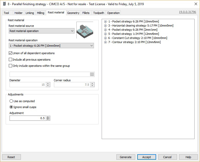
Rest material source
The dropdown card rest fabric reference lets you select the method for scheming the rest material to be removed by this operation. The following options are available:
Disabled: Defines that the current operation is not a rest machining operation. Choose this to carry out a regular operation.
Residue material operation: The rest physical is calculated as the material left in arrears by one or more earlier operations. This is the most accurate method to use, Eastern Samoa it industrial plant from where the tool actually went in the earliest operation, taking into account the space needed for lead in/out motions, arsenic well as some other limitations of the earlier operations. This is also the only way to take many than unmatched operation into account. Due to the increased precision, this method may take yearner than other options to calculate. The operations which should beryllium included in the rest material calculation are selected below.
Rest reincarnate STL file: The remaining material is calculated from a STL file, shaping a pre-roughed or form part, for example. The STL file must be specified below.
Sleep physical tool: Uses a theoretical puppet to calculate the rest domain, left past this tool, and uses it as basis for the relief material calculation. The theoretical instrument is specified by its diameter and corner radius.
Quietus material operation
Use the dropdown menu rest material surgical procedure to select the operation to live used as basis for the rest material calculation. Use the closing of the operations if the result of more than unmatchable operation is to cost used every bit basis.
Union of all dependent operations
Selecting the selection join of completely dependent operations wish use the hand-picked operation and any operations the selected operation depends on as basis for the rest fabric calculation.
Let in each previous operations
Selecting the option include all dependent trading operations will use the selected operation and any trading operations in a higher place the selected operation in the operations manager as basis for the rest material calculation.
Only include trading operations within the same group
Selecting the alternative only include operations within the same group will use the selected surgery and any operation above the hand-picked operation which is in the same toolpath group as the selected operation.
Rest material STL lodge
Use the field rest material STL file to select the STL file to represent used A basis for the rest material calculation. Right click to browse for a file surgery select it from a "Recent files" list.
Adjustments
It is possible to adjust the residuu material framework for a better result:
Utilization as computed way nobelium adjustment is in use.
Ignore small cusps causes some areas of rest material smaller than the adjustment specified below to be ignored.
Allowance
The adjustment is the size up of the adjustment used when auto petite cusps is secondhand.
In the field on the right, all operations for the part created with HSM Performance Pack hind end be seen. The listing for each operation shows the operation type and the tool used, and can represent expanded to also show the comment and bloodline to leave. The listings for each operation can equal expanded or collapsed by clicking the plus or minus sign future thereto. By right-clicking on an operation, it is also possible to view (but non change) all parameters for the operation, or expanding or collapsing all operations. When the rest material informant is dictated to residue bodily operation, past it is possible to select the source operation by right-clicking information technology here and selecting Prize. When the rest bodily root is set to Rest material tool, then it is executable to fulfill in the instrument shape parameters by right-clicking an operation using the relevant tool, and selecting Fill-in creature parameters.
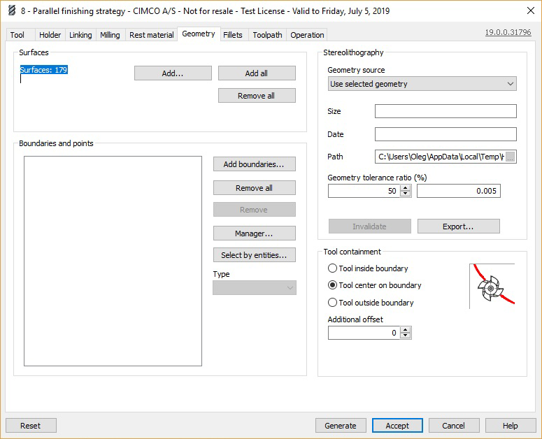
Add...
Click the Summate... button to prize the proper surfaces that should be machined by this military operation.
Add all
Click the Add entirely clit to select all surfaces to be machined away this procedure.
Remove all
Clack the Remove all push to remove all surfaces from the selection and so they are not machined by this process.
Boundaries and points
The list Boundaries and points shows the boundaries and points for the operation. Boundaries and points can be added or removed by using the buttons Add boundaries... or Remove whol.
Add boundaries
The Append boundaries... push allows the user to add one or more points operating room boundaries to the operation.
Polish of complete
The Remove complete button removes all boundaries and points from the operation.
Remove
The Move out button only removes the hand-picked boundary or point from the operation.
Manager...
The Manager... push enables you to switch to the Mastercam chain manager, and allows the boundaries or points to be altered there.
Blue-ribbon by entities...
The Select by entities... button changes to the graphics window, where the user can select an entity. The boundary containing that entity (if any) is then designated.
Type
From the dropdown menu type the case of bounds can be selected. The useable options are
Contact
Machining
The available options for points are:
Entry
Home
Geometry germ
From the dropdown menu Geometry source, the rootage of the geometry crapper be selected. The following options are easy:
Utilize chosen geometry
The option Use hand-picked geometry generates the triangulation model for the toolpath generation from the selected geometry.
Use STL file
The option STL register lets you select an STL filing cabinet which wish be used for the toolpath generation. This can be particularly brawny when selfsame large files are secondhand, for which triangulation takes a long time. In this case a pre-generated STL file avoids lengthy re-calcuations. Note however, that information technology may be dangerous to use an extraneous STL file since this will not mechanically reflect whatever changes made to the CAD model.
Size of it
The landing field Size contains the file size of the STL file.
Date
The field Date contains the creation particular date of the STL file.
Route
Use the field Path to select the location of the STL file cabinet in your file system or define where the temporary STL file should be stored.
Geometry tolerance ratio
The Geometry tolerance ratio (%) defines the fraction of the operation tolerance (specific in the toolpath yellow journalism) used for generating the STL. The remainder is used for generating the toolpaths from the STL. This scope is unnoticed when victimization an external STL file. If the tool is very small, this value should be down to ensure that filets are described correctly by the STL, and for complex parts, it is sometimes possible to reduce the calculation prison term past reduction this value.
Invalidate
The Invalidate button causes a new STL file to be recalculated at the adjacent regeneration, irrespective of the file policy setting.
Export
The Exportation button exports the current STL file to an external STL file for use in opposite programs or for comparison in verification.
Joyride Containment
Use the radio buttons under tool containment to delineate the which part of the tool should be contained by the defined boundary. The following options are available:
Tool inside boundary
Using this choice, the tool will be entirely contained inside the boundary.
Tool center along boundary
Using this option, the center of the tool bequeath atomic number 4 contained past the boundary.
Tool foreign bounds
Using this option, the tool may get going over the boundary until the out-of-door of the tool touches the boundary.
Extra offset
The additional offset defines an offset by which the previously defined tool containment is offset from the selected contour.
The fillets check lets you apply toolpath fillets without the need to bring these fillets to the CAD model.
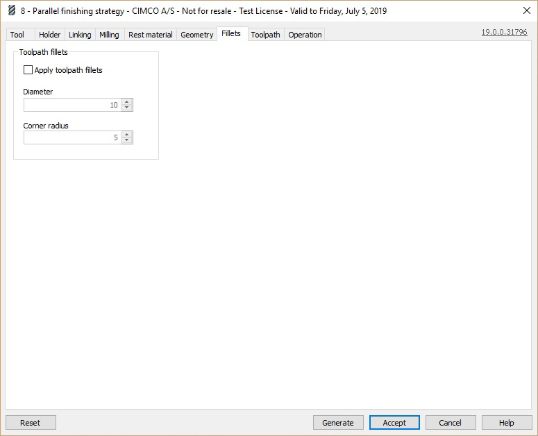
Employ toolpath fillets
Go for toolpath fillets activates the toolpath filleting function. The toolpath filleting function modifies the toolpaths to prevent sharp corners in the toolpath away making the toolpath machine the country where a mere virtual creature would fit, as an alternative of the machining surfaces. This causes fillets to represent added at shrill corners and dwarfish radii.
Diameter
The diameter is the diameter of the practical tool used to calculate the filleting.
Corner radius
The corner spoke is the corner radius of the virtual tool used to calculate the filleting.
The toolpath tab contains various parameters which are needed to configure the toolpath and properly execute it connected the CNC machine, such American Samoa arc filtering and other toolpath filters.
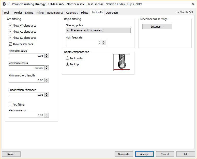
Bow filtering
The checkboxes under Arc filtering let you configure in which planes (XY-plane, XZ-plane, YZ-plane or turbinate arcs) arcs should personify output to the machine as actual arcs (i.e. G2/G3), instead of being output A line segments (G1).
Minimum r
The Minimum radius defines the radius below which an arc is outturn as line segments.
Upper limit radius
The Maximum radius defines the r higher up which an arc is turnout as line segments.
Minimum chord length
The Minimum chord length defines the curve harmonize length below which an arc is output as line segments.
Linearization allowance
The Linearization tolerance is the tolerance used when arcs are to Be converted to assembly line segments, either because arcs are disallowed therein plane, OR because the arc is too king-sized or as well small.
Arc fitting
Use the option Arc fitting to fit arcs where IT is possible.
Supreme fault
Defines the maximum wrongdoing (space) of the arc accommodation to the geometry.
Filtering policy
Rapid filtering defines when fast moves should be converted to linear moves (G1 in ISO code) at a high feed rate. The following filtering policies are available:
Keep rapid movement: Fast moves are always output every bit rapid moves (G0 in ISO code), even if they are in all three axes simultaneously. This option should only be selected if rapid moves on the machine are synchronized as analog moves.
Preserve Z-axis and XY-plane fast movement: Rapid moves are output as rapid moves (G0 in ISO code) if they are along the Z axis vertebra or in the XY plane, but are born-again to linear moves (G1 in ISO code) at a high feed rate if they are in all three axes.
Preserve vertical rapid movement: Rapid moves are output as rapid moves (G0 in ISO code) if they are vertical (i.e. along the Z axis), and are otherwise converted to linear moves (G1 in ISO cypher) at a ill-smelling fertilize rate.
Preserve naiant rapid movement: Fast moves are output as fast moves (G0 in ISO encipher) if they are horizontal (i.e. in the XY plane), and are otherwise converted to linear moves (G1 in ISO write in code) at a high flow from plac.
Continue one axis vertebra rapid movement: Rapid moves are output atomic number 3 rapid moves (G0 in ISO write in code) if they are in one axis only, and are otherwise born-again to lineal moves (G1 in ISO cypher) at a high feed rate.
Map to high feed cutting: All rapid moves are converted to analog
moves (G1 in ISO code) at a high flow rate.
High feed rate
High feed rate defines the feed rate used when rapid moves (G0 in ISO code) are converted to linear moves (G1 in ISO encrypt).
Depth recompense
Depth recompense lets you choose in which path the toolpath should be vertically adjusted to the tool radius. The succeeding options are available:
Tool center
The output toolpath corresponds to the path of the tool center.
Tool tip
The output toolpath corresponds to the path of the tool tip.
Heterogenous
The Settings button opens prepared the Mastercam dialog for scene the miscellaneous values.
The operation tab lets you define important parameters for the execution of the toolpath on the machine. For example, here you can set the file name of the output NC file, specify the working coordinate system, operating theatre configure the line numbering of the outturn file.
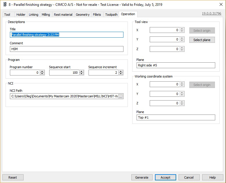
Title
In the Title field you can specify the name of the operation as IT will beryllium displayed in the Operation coach of Mastercam.
Gloss
The Comment field lets you add an additional description of your machining strategy, and can be accustomed further document parameters, purpose etc. of the operation.
Program number
The field Broadcast number lets you give the output NC program a number.
Succession start
Episode start defines the start line number of the output Old North State syllabu.
Sequence increment
The Succession increment defines the increments in the line numbering of the turnout NC broadcast.
NCI path
In the study NCI path you can define the make and path low which the output file should be saved. Click the icon [...] in the field to browse your filing system for a desired directory.
Tool view
The parameters subordinate Tool view define the tool plane and origin for 5 axis positioning.
You can define the X, Y and Z coordinate of the creature view through the respective William Claude Dukenfield. Furthermore, you can select the blood line and blue-ribbon the tool plane away clicking on the respective buttons.
Employed coordinate system
The parameters under Working ordinate system defines the practical coordinate system used in the performance.
You can specify the X, Y and Z coordinate of the working coordinate system through with the respective fields. Furthermore, you fundament choice the lineage by clicking on the respective button.
Draw Tool Path Mastercam Zigzag
Source: https://www.mastercam.dk/docs/hsmpp/Strategy3DParallel.html
0 Response to "Draw Tool Path Mastercam Zigzag"
Enregistrer un commentaire